
by Admin | Mar 18, 2026 | Services
Turnaround-Ready Inspection Teams: Ensuring Safe, Efficient Plant Shutdowns Hello Industrial Partners! In industrial operations, few events are as critical—and as complex—as a plant turnaround. These planned shutdowns are essential for maintenance, inspections,...

by Admin | Mar 11, 2026 | Services
Concrete Testing & Geotechnical Services: Why They Are Critical for Reliable Construction Hello Industrial Partners! In any construction project, the strength and stability of a structure depend on two key factors: the quality of the materials used and the...
by Admin | Mar 4, 2026 | Services
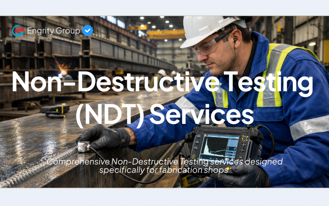
Comprehensive Non-Destructive Testing services designed specifically for fabrication shops Hello Fabrication Partners! In steel and bridge fabrication, every weld carries more than structural load — it carries safety, compliance, liability, and the reputation you’ve...

by Admin | Feb 25, 2026 | Services
Build It Right the First Time | Engrity Inspection Civil Services Hello Construction Partners, In construction, the strength of a structure is determined long before the final concrete pour or steel installation. It begins with disciplined quality control, proper...

by Admin | Feb 18, 2026 | Services
Power You Can Trust. Precision You Can Prove Hello Industrial Partners, In today’s industrial landscape, Electrical & Instrumentation (E&I) systems are the backbone of every successful project. From power distribution and grounding systems to complex control...