
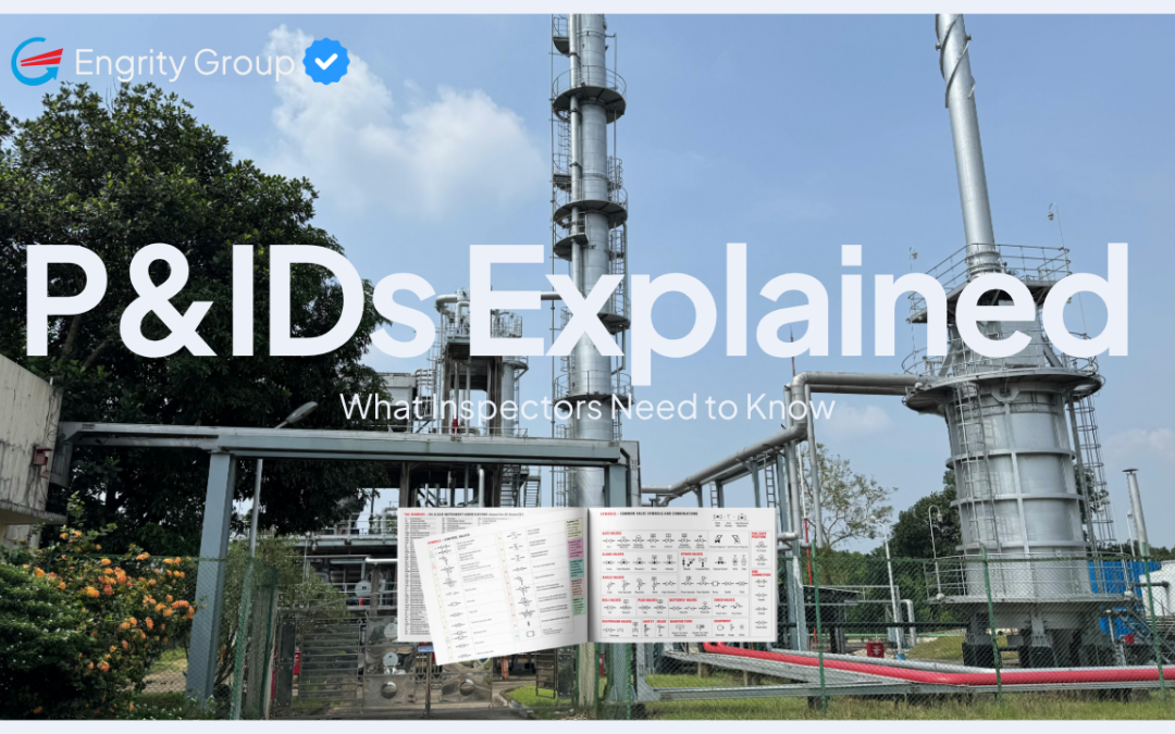
P&IDs Explained for QA/QC Inspectors: A Practical Guide to Piping & Instrumentation Diagrams
Hello Everyone!
Understanding Piping and Instrumentation Diagrams (P&IDs) is an essential skill for QA/QC inspectors, welding inspectors, NDT technicians, construction professionals, and commissioning teams working on industrial projects.
A Piping and Instrumentation Diagram, commonly referred to as a P&ID, provides a detailed graphical representation of the piping, equipment, valves, instrumentation, control systems, and process connections within a facility or process system.
For inspectors, a P&ID is more than an engineering drawing. It can serve as an important reference during construction inspection, piping inspection, system walkdowns, pressure testing, commissioning, punch-list activities, and documentation review.
Knowing how to read and interpret a P&ID allows inspectors to better understand what is being constructed, how individual components connect, and how the completed system is intended to function.
What Is a P&ID?
A Piping and Instrumentation Diagram (P&ID) is an engineering drawing that illustrates the relationships between piping, equipment, valves, instrumentation, and control systems within a process.
P&IDs are commonly used in industries such as:
- Oil and gas
- Petrochemical
- Energy and power generation
- LNG
- Mining
- Chemical processing
- Water and wastewater
- Manufacturing
- Industrial construction
- Infrastructure
- Pharmaceutical and process facilities
Unlike a basic layout drawing, a P&ID provides information about how components are connected and how the process system is controlled.
Depending on the project and engineering standard, a P&ID may identify:
- Piping systems
- Pipe sizes
- Line numbers
- Piping specifications
- Flow direction
- Valves
- Pumps
- Tanks
- Pressure vessels
- Heat exchangers
- Instruments
- Control loops
- Drains and vents
- Equipment connections
- Process connections
- Safety devices
- Utility connections
The exact symbols, identification systems, and information presented can vary between projects, so inspectors should always refer to the project’s approved drawings, specifications, legends, and applicable standards.
Why Are P&IDs Important for QA/QC Inspectors?
QA/QC inspectors are often required to verify that construction and installation activities conform to approved drawings, specifications, codes, standards, and project requirements.
A P&ID can provide the inspector with the system-level context needed to perform those activities effectively.
For example, an inspector may be looking at a section of piping in the field. The physical piping alone may not show the complete purpose of the system.
By reviewing the applicable P&ID, the inspector can determine:
- What system the piping belongs to
- Where the line originates
- Where it terminates
- What equipment it connects to
- What valves are installed
- What instruments are associated with the line
- What other systems it interfaces with
- Where potential test boundaries may exist
- Whether the field installation corresponds with the documented design
This makes the P&ID an important reference for field verification and system understanding.
What Information Does a P&ID Show?
A P&ID contains a significant amount of information. The specific information will vary depending on the project, but several elements are commonly encountered.
1. Piping
P&IDs identify piping connections between equipment and process systems.
Depending on the project’s drawing conventions, piping information may include:
- Line numbers
- Nominal pipe size
- Piping class or specification
- Service description
- Flow direction
- Insulation requirements
- Heat tracing
- Connections
- Branches
- Drains
- Vents
For QA/QC inspectors, line identification is particularly important because it allows field piping to be cross-referenced with other project documentation.
2. Line Numbers
Line numbers are commonly used to identify individual piping systems or segments.
A line number may contain information relating to:
- Pipe size
- Service
- Piping specification
- Sequence or identification number
- Insulation requirements
- Design information
The format is project-specific.
Inspectors should avoid assuming that a line-number format means the same thing on every project. Always review the applicable project legend or line list.
Line numbers can be used to cross-reference:
- P&IDs
- Isometric drawings
- Line lists
- Test packages
- Inspection and Test Plans
- Pressure-test documentation
- Welding documentation
- NDT records
- Material documentation
3. Equipment
P&IDs identify major process equipment connected to the piping system.
This can include:
- Pumps
- Tanks
- Pressure vessels
- Heat exchangers
- Compressors
- Filters
- Separators
- Reactors
- Skids
- Furnaces
- Other process equipment
Equipment tags are typically used to uniquely identify equipment.
For example, a pump may have an equipment tag that allows the inspector to cross-reference the P&ID with equipment documentation, inspection records, datasheets, and other drawings.
4. Valves
Valves are a major component of many P&IDs.
Depending on the system, an inspector may encounter:
- Gate valves
- Globe valves
- Ball valves
- Butterfly valves
- Check valves
- Control valves
- Relief valves
- Isolation valves
- Drain valves
- Vent valves
The P&ID helps identify where valves are located within the process and how they relate to the surrounding piping and equipment.
During field inspection, the inspector may use the P&ID to verify that the correct valve is installed in the correct location and that the valve identification corresponds with the project documentation.
5. Instrumentation
Instrumentation is another important part of a P&ID.
Depending on the process, instruments may measure or control:
- Pressure
- Temperature
- Flow
- Level
- Differential pressure
- Other process variables
Instrumentation symbols and tags can indicate how instruments interact with the process and control system.
For QA/QC and commissioning teams, understanding these connections can help during:
- Instrument verification
- Loop checks
- System walkdowns
- Commissioning activities
- Functional testing
- Punch-list inspections
6. Control Loops
P&IDs can also illustrate control loops and signal relationships.
For example, a process may use a pressure transmitter to measure pressure and send a signal to a control system, which then operates a control valve.
The P&ID provides a graphical representation of these relationships.
This becomes particularly useful during commissioning and troubleshooting because the inspector or commissioning team can understand how the components are intended to interact.
7. Flow Direction
Flow arrows are used to indicate the intended direction of process flow.
Understanding flow direction can help an inspector determine whether:
- Piping has been installed correctly
- Equipment connections correspond with the design
- Valves are oriented correctly
- Components are connected to the appropriate system
- The field installation corresponds with the approved design
Flow direction should always be interpreted in conjunction with the project’s drawings and engineering requirements.
P&ID vs. PFD: What Is the Difference?
One of the most common questions for people learning engineering drawings is the difference between a P&ID and a PFD.
What Is a PFD?
A Process Flow Diagram (PFD) provides a higher-level representation of a process.
A PFD typically focuses on:
- Major process equipment
- Main process streams
- Process flow
- Major operating information
- Overall process relationships
It is primarily used to understand the overall process.
What Is a P&ID?
A P&ID provides a significantly more detailed representation of the process system.
It can include:
- Piping
- Valves
- Instruments
- Control loops
- Equipment connections
- Drains
- Vents
- Process interfaces
- Other detailed system information
Simple way to remember the difference:
PFD = Understand the overall process.
P&ID = Understand how the process system is connected and controlled.
Both documents can be important, but they serve different purposes.
How QA/QC Inspectors Use P&IDs in the Field
P&IDs can support several inspection activities throughout a project lifecycle.
1. Construction Inspection
During construction, inspectors may use P&IDs to understand how individual piping sections and equipment are intended to connect.
This can help with field verification of:
- Equipment connections
- Piping routes
- Valves
- Instruments
- Branch connections
- Drains
- Vents
- System interfaces
The P&ID should generally be used together with the more detailed construction drawings applicable to the inspection.
2. Piping Walkdowns
System walkdowns are an important activity during construction completion and commissioning.
During a walkdown, inspectors may compare the physical installation against approved project documentation.
A P&ID can help the team understand the intended system configuration.
Typical walkdown activities may include verifying:
- Equipment identification
- Valve identification
- Piping connections
- Instruments
- System boundaries
- Missing components
- Incorrect installations
- Accessible components
- Potential punch-list items
The P&ID does not replace detailed drawings or field inspection requirements, but it provides valuable system-level context.
3. Pressure Testing
P&IDs can also help teams understand potential pressure-test boundaries.
Before pressure testing, the applicable test package and project documentation should establish the approved test boundary and requirements.
The P&ID can assist with identifying:
- Equipment within the system
- Isolation points
- Connected piping
- Valves
- Branches
- Potential interfaces with other systems
- Vents and drains
However, inspectors should never determine a test boundary from a P&ID alone when project-specific test documentation or engineering instructions are available.
Always follow the approved test package, procedures, specifications, and project requirements.
4. Mechanical Completion
During mechanical completion activities, P&IDs can help teams verify whether the system has been installed in accordance with the intended design.
Potential verification activities include:
- Equipment installation
- Piping connections
- Valve installation
- Instrument installation
- Drains and vents
- Identification
- System interfaces
Completed inspection records can then be cross-referenced with the applicable system documentation.
5. Commissioning
During commissioning, understanding the P&ID becomes even more important.
Commissioning teams need to understand how equipment and systems interact before they are placed into service.
P&IDs can support activities such as:
- System walkdowns
- Loop checks
- Functional testing
- Equipment verification
- Valve verification
- System turnover
- Punch-list closeout
- Startup preparation
For inspectors and commissioning personnel, being able to trace a system through the P&ID can significantly improve understanding of the field installation.
Cross-Referencing P&IDs With Other Documents
One of the most important skills for a QA/QC inspector is knowing that no single drawing tells the entire story.
P&IDs should often be cross-referenced with other project documents.
These may include:
Isometric Drawings
Isometric drawings provide detailed information about individual piping runs, including dimensions, fittings, weld locations, elevations, and other fabrication information.
Line Lists
Line lists can provide detailed information about individual piping systems and their design requirements.
Equipment Datasheets
Equipment datasheets provide information about specific equipment items.
Inspection and Test Plans
ITPs establish inspection and testing requirements, hold points, witness points, documentation requirements, and other project-specific requirements.
Specifications
Project specifications define technical requirements that may not be fully represented on the P&ID.
Welding Documentation
Depending on the scope, inspectors may need to cross-reference:
- Weld maps
- Welding procedures
- Welder qualifications
- WPS
- PQR
- NDT reports
- Material documentation
Test Packages
Test packages contain the specific requirements and documentation associated with pressure testing or other system tests.
The Importance of Revision Control
One of the most important rules when working with engineering drawings is to make sure you are using the latest approved revision.
A field inspector can perform a technically correct inspection against an outdated drawing and still create a documentation or compliance issue.
Before beginning an inspection, verify:
- Drawing number
- Revision number
- Drawing status
- Approval status
- Effective date
- Applicable project area
- Applicable system
If there is uncertainty about which drawing is current, confirm with the appropriate project document-control or engineering team.
Common P&ID Mistakes Inspectors Should Avoid
Understanding P&IDs is important, but knowing what not to do is equally important.
Mistake 1: Using an Outdated Revision
Always verify the current approved revision.
Mistake 2: Treating a P&ID Like an Isometric
A P&ID is not intended to provide every physical dimension or fabrication detail.
Use the appropriate isometric, layout, fabrication drawing, or other applicable document for detailed field information.
Mistake 3: Assuming Symbols Are Universal
Symbols can vary depending on project standards, engineering practices, and drafting conventions.
Review the project’s:
- Legend
- Drawing notes
- Design standards
- Applicable codes
- Engineering documentation
Mistake 4: Inspecting Without Understanding the System Boundary
Before performing a system walkdown or inspection, understand which portion of the system is included in the scope.
This is particularly important for testing and commissioning activities.
Mistake 5: Relying on One Document
A P&ID should generally be cross-referenced with the applicable project documentation.
An inspector should understand which document controls each specific inspection requirement.
A Practical P&ID Review Process for Inspectors
A simple workflow can help inspectors approach P&IDs systematically.
Step 1: Identify the System
Determine what process system or equipment you are inspecting.
Step 2: Locate the P&ID
Find the applicable P&ID and verify the drawing number and revision.
Step 3: Identify the Equipment
Locate the relevant pumps, vessels, tanks, exchangers, or other equipment.
Step 4: Trace the Piping
Follow the piping from the starting point through the system.
Pay attention to:
- Line numbers
- Pipe sizes
- Branches
- Valves
- Flow direction
- Equipment connections
Step 5: Identify Instruments
Review the instrumentation associated with the system.
Understand how instruments relate to the piping and equipment.
Step 6: Identify Interfaces
Determine where the system connects to:
- Other process systems
- Equipment
- Utilities
- Drains
- Vents
- Instrumentation
- Other project scopes
Step 7: Cross-Reference Documentation
Review the applicable:
- Isometrics
- Line lists
- ITPs
- Specifications
- Test packages
- Equipment documentation
- Inspection records
Step 8: Compare With the Field
During the walkdown, compare the physical installation with the approved documentation.
Document discrepancies according to the project’s established process.
P&IDs and Welding Inspection
For welding inspectors, P&IDs can provide useful system context even though detailed weld information is generally found on other drawings and documentation.
A welding inspector may use the P&ID to understand:
- Which piping system a line belongs to
- What equipment the piping connects to
- System boundaries
- Relevant piping interfaces
- Process service
- Connections between components
The inspector would then typically rely on applicable fabrication drawings, isometrics, weld maps, WPSs, project specifications, and other approved documentation for detailed welding inspection requirements.
This distinction is important:
The P&ID provides system context; detailed welding documents provide fabrication and inspection requirements.
P&IDs and NDT Inspection
NDT personnel may also encounter P&IDs during project execution.
For example, an NDT technician may be assigned to examine welds associated with a particular piping system.
The P&ID can help establish the broader system context, while detailed drawings and inspection documentation identify the specific welds or components requiring examination.
Depending on the project, NDT documentation may include:
- Weld maps
- NDT requests
- Inspection reports
- Isometric drawings
- Line numbers
- Weld numbers
- Examination requirements
- Acceptance criteria
The applicable project requirements should always determine the examination scope and method.
P&IDs and Commissioning Walkdowns
Commissioning teams often rely heavily on accurate system documentation.
A commissioning walkdown may involve physically tracing a system and confirming that the installed components correspond with the approved documentation.
During these activities, teams may identify:
- Missing valves
- Incorrect tags
- Missing instruments
- Incorrect connections
- Open-ended piping
- Missing drains or vents
- Installation discrepancies
- Incomplete insulation
- Access issues
- Outstanding punch-list items
A properly controlled P&ID can provide a useful roadmap for this process.
Why P&ID Knowledge Matters for QC Inspectors
For a QA/QC inspector, technical inspection is not only about looking at individual components.
It is also about understanding how those components fit into the larger system.
An inspector who understands P&IDs can better connect:
Drawing → System → Component → Inspection → Test → Documentation
This system-level understanding can improve communication between:
- Engineering
- Construction
- QA/QC
- NDT
- Commissioning
- Operations
- Project management
It can also make field discussions more productive because the inspector can communicate using the project’s established equipment tags, line numbers, system boundaries, and drawing references.
P&ID Reading Skills for New Inspectors
If you are a new QA/QC or welding inspector, learning P&IDs can initially seem overwhelming.
Start with the basics.
Focus first on learning how to identify:
- Equipment tags
- Line numbers
- Pipe sizes
- Valves
- Flow direction
- Instruments
- Equipment connections
- Drains and vents
- System boundaries
- Drawing revisions
Once you are comfortable identifying these elements, begin tracing complete systems from one piece of equipment to another.
With practice, you can gradually develop the ability to understand larger and more complex process systems.
QA/QC Tip: Always Verify the Latest Approved Revision
One of the simplest habits an inspector can develop is to check the drawing revision before starting the inspection.
Do not assume that the drawing available in an old folder, email attachment, printed package, or previous inspection record is still current.
A good document-control habit is:
Check the drawing number → Check the revision → Check the status → Confirm applicability → Perform the inspection.
This simple process can help prevent unnecessary rework and documentation issues.
Frequently Asked Questions About P&IDs
What does P&ID stand for?
P&ID stands for Piping and Instrumentation Diagram.
What is the purpose of a P&ID?
A P&ID provides a detailed representation of piping, equipment, valves, instrumentation, control systems, and their relationships within a process system.
Do QA/QC inspectors need to know how to read P&IDs?
P&ID knowledge is highly useful for QA/QC inspectors working on piping, mechanical, process, industrial, construction, and commissioning projects. The specific requirements depend on the inspector’s role and project scope.
What is the difference between a P&ID and an isometric drawing?
A P&ID focuses primarily on process relationships, piping systems, equipment, valves, and instrumentation.
An isometric drawing provides more detailed information about the physical fabrication and installation of a particular piping section.
What is the difference between a P&ID and a PFD?
A PFD provides a higher-level overview of the process and major equipment.
A P&ID provides more detailed information about piping, valves, instrumentation, equipment connections, and controls.
Can a P&ID be used to determine a pressure-test boundary?
A P&ID can help provide system context and identify connected components, but the approved project test package, procedure, engineering requirements, and applicable documentation should establish the actual test boundary.
Should inspectors use the P&ID alone?
No. P&IDs should be cross-referenced with applicable project drawings, specifications, ITPs, procedures, test packages, and other approved documentation.
Final Takeaway
For QA/QC inspectors, understanding P&IDs is an important part of developing strong technical and field-inspection skills.
A P&ID helps provide the bigger picture:
What is the system?
What equipment is connected?
Where does the piping go?
What valves and instruments are involved?
How does the system interact with other components?
When combined with isometrics, specifications, ITPs, test packages, equipment documentation, and other approved project records, P&IDs can help inspectors better understand the system they are inspecting and support effective construction, inspection, testing, and commissioning activities.
Whether you are a QA/QC Inspector, Welding Inspector, NDT Technician, Construction Inspector, or Commissioning Professional, developing the ability to read and interpret P&IDs can be a valuable addition to your technical skill set.
At Engrity Group, we support industrial, fabrication, infrastructure, and construction projects with professional QA/QC inspection and NDT services across Canada.
Follow Engrity Group for more practical resources covering QA/QC, welding inspection, NDT, construction inspection, engineering drawings, inspection documentation, codes, standards, and industry careers.
Engrity Group
Building Confidence Through Quality and Compliance.
Experience the Difference
Contact
Phone
+1 (780) 800-6297
info@engrity.com
Address:
201-9403 63 Ave NW, Edmonton, AB T6E 0G2