
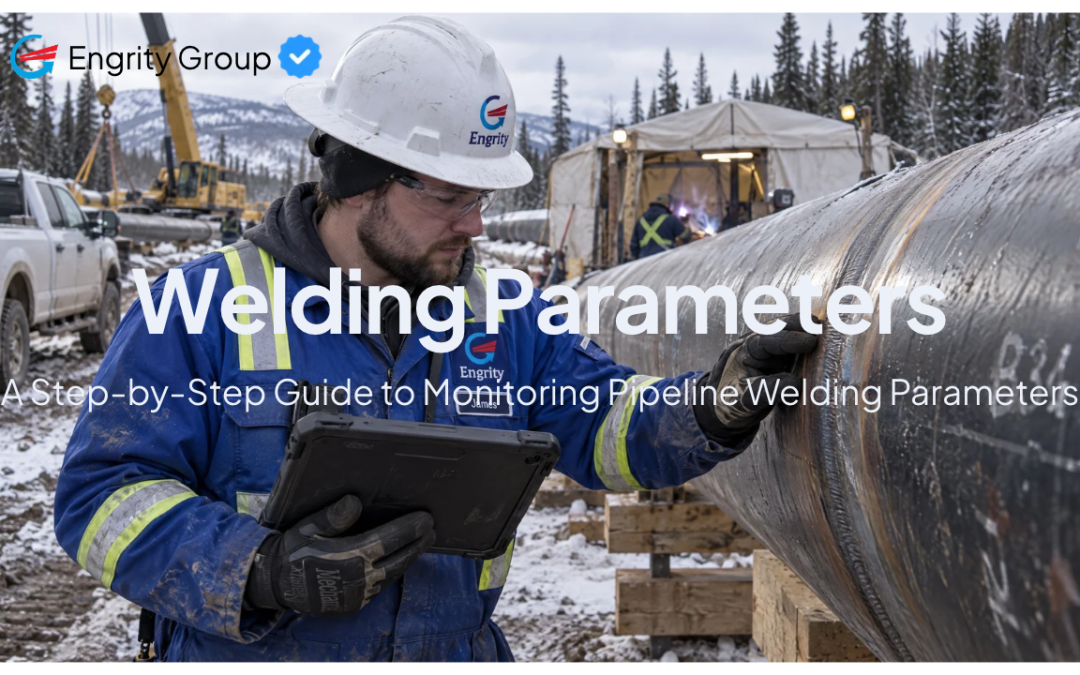
Welding Parameters for QC Inspectors: A Complete Guide to Welding Parameters
Welding quality in pipeline and industrial construction depends on more than visual inspection. It also requires verifying that welding activities are performed within the limits established by the approved Welding Procedure Specification (WPS) and applicable project requirements.
For Quality Control (QC) Inspectors, understanding how to measure welding current, voltage, travel speed, preheat temperature, interpass temperature, and heat input is essential for monitoring welding operations and identifying deviations before they affect weld quality.
This guide explains the key welding parameters, the instruments used to measure them, the formulas required for field calculations, and the documentation practices that support effective welding inspection.
1. Understanding the Welding Procedure Specification (WPS)
Before measuring any welding parameters, the inspector must review the approved WPS applicable to the weld being inspected.
A WPS establishes the qualified welding conditions and ranges that must be followed for the applicable welding process, material, joint, and position.
Depending on the procedure and applicable requirements, a WPS may specify:
- Welding process, such as Shielded Metal Arc Welding (SMAW), Gas Metal Arc Welding (GMAW), or Flux-Cored Arc Welding (FCAW).
- Base material and material thickness ranges.
- Joint design and welding position.
- Electrode or filler metal classification and diameter.
- Welding current and polarity.
- Voltage ranges, where applicable.
- Travel speed or heat input restrictions, where specified.
- Minimum preheat temperature.
- Maximum interpass temperature.
- Welding progression, including uphill or downhill progression where applicable.
- Shielding gas and flow rate, where applicable.
- Other essential or supplementary requirements applicable to the project.
For example, a current reading of 180 amperes may be acceptable for one electrode and welding position but unsuitable for another. The approved procedure and applicable requirements determine the acceptable limits.
2. Measuring Equipment Calibration and Verification
Accurate inspection starts with reliable measuring equipment. Incorrect readings can lead to false acceptance, unnecessary rejection, or failure to identify a welding deviation.
Before taking measurements, verify the condition and suitability of the instruments.
Equipment commonly used for welding parameter inspection
| Instrument | Primary purpose |
|---|---|
| Clamp meter or suitable welding current meter | Measures welding current |
| Suitable voltmeter or welding parameter monitoring instrument | Measures voltage |
| Stopwatch or timer | Measures arc-on time |
| Measuring tape or ruler | Measures weld length |
| Contact pyrometer or temperature-indicating device | Measures or verifies temperature |
| Infrared thermometer | Measures surface temperature without contact, subject to instrument limitations |
| Data logger or welding monitoring system | Records parameters over time, where available |
Calibration checklist
Before using an instrument:
- Confirm that the instrument has the required calibration certificate.
- Check that calibration remains valid according to the project or quality management requirements.
- Verify the instrument identification number against the calibration records.
- Inspect the instrument, probes, leads, clamps, and accessories for damage.
- Confirm the measurement range, resolution, and accuracy are suitable for the intended measurement.
- Check any required functional verification before use.
- Record the instrument identification and relevant readings in the inspection documentation.
A calibration certificate alone does not guarantee that an instrument is suitable for every measurement. The inspector must also consider its range, accuracy, condition, and method of use.
3. Welding Current (Amperage)
Welding current, measured in amperes (A), influences the energy delivered during welding and can affect penetration, deposition, and weld bead characteristics.
The acceptable current depends on the welding process, consumable, electrode diameter, joint configuration, welding position, and approved procedure.
How to measure welding current
A suitable calibrated clamp meter or welding current measuring instrument can be used, provided it is designed for the measurement and compatible with the welding equipment.
- Confirm the applicable WPS and its permitted current range.
- Verify that the current measuring instrument is suitable for the welding process.
- Position the instrument according to the manufacturer's instructions and approved electrical safety procedures.
- When using a clamp meter, clamp around a single conductor, not around both the outgoing and return conductors together.
- Observe and record the current while welding under representative operating conditions.
- Where current fluctuates, record the relevant readings or ranges using the method required by the project.
- Compare the results with the applicable WPS limits.
Important: Welding current can fluctuate during operation. A single instantaneous reading may not represent the entire pass. If continuous monitoring or averaged values are required, use a suitable monitoring instrument and the prescribed recording method.
Do not handle exposed electrical conductors or place instruments near the arc without appropriate protection and an approved measurement method.
Example: Current verification
Assume the approved WPS specifies a permitted current range of 160–200 A. The inspector records the following representative readings:
- Reading 1: 175 A
- Reading 2: 182 A
- Reading 3: 188 A
All three readings fall within the assumed range. However, this does not establish compliance with every welding requirement. The inspector must also verify the other applicable parameters and determine whether the sampling method satisfies the project requirements.
If the current exceeds the permitted range, document the deviation and follow the project's nonconformance or escalation procedure.
4. Welding Voltage
Welding voltage, measured in volts (V), is another important parameter that must be monitored when required by the applicable WPS or project specifications.
Voltage can influence arc characteristics, bead profile, and the amount of energy delivered during welding.
How to measure welding voltage
Use a suitable calibrated voltmeter or welding monitoring system capable of measuring the required voltage.
- Review the WPS voltage limits, if specified.
- Confirm that the instrument is suitable for the welding equipment and measurement method.
- Take readings using approved connections or monitoring equipment.
- Measure under representative welding conditions.
- Record the readings and compare them with the applicable requirements.
Arc voltage can vary throughout a weld. Voltage measured at the power source may differ from the voltage at the arc because of cable resistance and other electrical losses.
For this reason, the inspector must understand what the instrument is measuring and use the method required by the project. Do not assume that a power-source display and a direct arc-voltage measurement are interchangeable.
Example: Voltage verification
Assume the applicable WPS specifies a voltage range of 20–26 V.
A representative reading of 24 V is within that range.
The inspector should document the reading, the measurement method, and any additional readings required by the project procedure.
5. Measuring Welding Travel Speed
Travel speed is the speed at which the welding arc progresses along the joint. It is commonly expressed in inches per minute (in/min) or millimetres per minute (mm/min).
Travel speed affects the amount of energy delivered per unit length of weld. If travel speed decreases while voltage and current remain constant, the nominal arc energy per unit length increases. If travel speed increases, nominal arc energy decreases.
Formula for travel speed
Field measurement procedure
- Identify the measurement segment: Select a representative weld segment or pass that can be measured accurately.
- Mark the starting point: Mark the beginning of the segment whose weld length will be measured.
- Start the timer: Start timing when the arc begins depositing weld metal on the selected segment.
- Mark the endpoint: Stop the timer when the arc finishes the measured segment, then mark the endpoint.
- Measure the weld length: Measure the completed weld length along the actual weld path (circumferentially on pipe).
- Calculate the travel speed: Use the formula and record the result with units.
Important: The measured distance and elapsed time must correspond strictly to the same continuous arc-on interval.
Worked example: Travel speed calculation
Assume the inspector records a weld length of 8 inches and an arc-on time of 40 seconds.
= 480 ÷ 40
= 12 in/min
Converting inches per minute to millimetres per minute:
12 in/min ≈ 305 mm/min
The calculated travel speed is approximately 305 mm/min.
Why should different passes be measured?
For multi-pass pipeline welding, representative root, hot, fill, and cap passes may have different travel speeds and operating conditions. Where required by the project, evaluate the relevant passes separately rather than assuming one measurement represents the whole weld.
6. Preheat Temperature
Preheat is the heating of the base material before welding begins. The required preheat temperature depends on the material, thickness, welding procedure, and applicable code or project specification.
Preheat helps control cooling conditions and can reduce the risk of hydrogen-assisted cracking where susceptible conditions exist.
How to verify preheat temperature
Depending on the approved procedure, suitable instruments may include contact pyrometers, temperature-indicating crayons, or calibrated infrared thermometers.
- Review the required minimum preheat temperature.
- Confirm the approved measurement method and distance from the joint.
- Measure the material temperature immediately before welding begins.
- Verify that the required temperature is achieved and maintained throughout the joint area.
- Record the result and measurement locations.
Example: Preheat verification
Assume the WPS requires a minimum preheat temperature of 100°C. The inspector measures the material temperature at the specified location and obtains 115°C.
Since 115°C is above 100°C, the measured temperature meets that particular minimum requirement. However, verify any maximum interpass limits and location restrictions before accepting the condition.
7. Interpass Temperature
Interpass temperature is the temperature of the weld area or adjacent material before the next weld pass is deposited. Control helps maintain the thermal conditions qualified by the welding procedure.
How to measure interpass temperature
- Confirm the applicable temperature limits (minimum, maximum, or both).
- Identify the specified measurement location.
- Measure the temperature before depositing the next pass using an approved instrument.
- Record the temperature and associated pass ID.
- Confirm compliance before welding continues.
Example: Interpass temperature verification
Assume the WPS specifies an interpass temperature between 100°C and 250°C. The inspector records a temperature of 185°C before the next pass.
The reading falls within the compliant range of 100–250°C. If the reading were 270°C, it would exceed the maximum, requiring welding to pause until cooled within limits.
Infrared thermometer considerations
Infrared thermometers estimate surface temperature based on emitted infrared energy. Accuracy can be affected by surface emissivity, scale, oxidation, measurement distance, and viewing angle. Always ensure emissivity settings are configured correctly for bare or oxidized steel.
8. Heat Input and Arc Energy Calculations
Arc energy is the electrical energy supplied per unit length of weld. Heat input refers to arc energy adjusted by a thermal efficiency factor, depending on the applicable code.
A. Arc energy formula in imperial units
When voltage is in volts, current is in amperes, and travel speed is in inches per minute:
B. Arc energy formula in metric units
When travel speed is expressed in millimetres per minute:
Worked example: Calculating arc energy in kJ/in
Assume representative parameters: Voltage: 24 V, Current: 180 A, Travel speed: 12 in/min.
E = 259,200 ÷ 12,000
E = 21.6 kJ/in
Converting arc energy from kJ/in to kJ/mm
Since one inch equals 25.4 millimetres:
E = 21.6 ÷ 25.4
E ≈ 0.85 kJ/mm
Worked example: Direct metric calculation
Using 24 V, 180 A, and a travel speed of 305 mm/min:
E = 259,200 ÷ 305,000
E ≈ 0.85 kJ/mm
C. Applying a thermal efficiency factor
Where the standard specifies heat input adjusted by efficiency (η):
Example: Efficiency calculation
If a calculation requires an efficiency factor of 0.8 (typical for SMAW):
H = 17.28 kJ/in
9. Welding Progression, Position, and Consumables
Beyond electrical readings, verify non-electrical essential variables:
- Progression: Confirm uphill or downhill progression per the WPS.
- Welding Position: Ensure position (e.g., 5G, 6G) complies with procedure and welder qualifications.
- Consumables: Verify classification, diameter, batch numbers, and proper baking/storage conditions.
- Gas Flow & Fit-Up: Check shielding gas flow, root face, root gap, and alignment.
10. Documenting Actual Welding Parameters
Measurements must be traceably recorded to verify compliance during quality audits.
Example inspection record
| Parameter | Illustrative result |
|---|---|
| Weld identification | W-101 |
| WPS | WPS-001 Rev. 3 |
| Welding current | 180 A |
| Voltage | 24 V |
| Measured weld length | 8 in |
| Arc-on time | 40 sec |
| Calculated travel speed | 12 in/min (305 mm/min) |
| Calculated nominal arc energy | 21.6 kJ/in (0.85 kJ/mm) |
| Preheat / Interpass temperature | 115°C / 185°C |
| Instrument IDs | CL-092 / MM-041 / PY-014 |
| Inspection disposition | Accepted to WPS Limits |
11. What to Do When a Parameter Is Outside WPS Limits
- Verify the reading: Check lead connections, instruments, and units.
- Confirm the requirement: Re-check the WPS revision and tolerance ranges.
- Communicate the deviation: Notify the welding supervisor immediately.
- Document the finding: Record actual values, pass ID, and joint ID.
- Follow escalation procedures: Issue a Non-Conformance Report (NCR) if required.
- Verify corrective actions: Ensure authorized engineering disposition is satisfied before releasing the joint.
12. Common Welding Parameter Inspection Mistakes
- Using uncalibrated instruments: Displays can be misleading without certified calibration.
- Measuring voltage at power source: Cable drops make arc voltage appear higher than it is.
- Including arc-off pauses in travel speed: Inflates arc time and skews heat input.
- Evaluating only one pass: Parameters vary greatly between root, hot, fill, and cap passes.
- Mixing units: Blending inches and millimetres ruins calculations.
- Ignoring surface conditions for temperature: Scale and reflectivity distort IR thermometer readings.
13. QC Inspector's Field Checklist
Before welding
- Confirm approved WPS revision and joint fit-up.
- Verify consumable type, diameter, and baking storage controls.
- Check measuring instruments calibration status.
- Verify preheat temperature across the specified soak band.
During welding
- Measure arc current on a single conductor during steady welding.
- Verify arc voltage as close to the joint as safe.
- Record continuous arc-on time and deposit length for travel speed.
- Verify interpass temperature prior to subsequent passes.
After measurement
- Calculate travel speed and arc energy / heat input.
- Compare values against WPS tolerance limits.
- Record instrument IDs, weld IDs, and welder stamp numbers.
- Complete and sign inspection reports.
14. Frequently Asked Questions
What welding parameters should a QC Inspector monitor during pipeline welding?
Current, voltage, travel speed, preheat temperature, interpass temperature, progression direction, and calculated arc energy or heat input.
How do you calculate welding travel speed?
Multiply the deposited weld length by 60 and divide by continuous arc-on seconds: (Length × 60) ÷ Time (sec).
Is arc energy the same as heat input?
Not necessarily. Arc energy measures electrical energy input. Heat input adjusts arc energy by the thermal efficiency factor (η) of the welding process.
Conclusion: Consistent Measurement Supports Better Welding Quality
Accurate welding parameter measurement is an important part of pipeline and industrial construction quality control. By using suitable instruments, following approved measurement methods, calculating travel speed and arc energy correctly, controlling temperature, and maintaining traceable inspection records, QC Inspectors help verify that welding activities comply with the applicable requirements.
Engrity Group Inc.
Our CWB Level 1 and Level 2 Welding Inspectors support pipeline and industrial construction projects across Western Canada.
Competent. Reliable. Fast.
Technical note: This article is intended for general educational purposes. It does not replace the approved WPS, applicable welding codes and standards, project specifications, or the manufacturer's instrument instructions. Always follow the requirements governing the specific project and welding operation.
Experience the Difference
Contact
Phone
+1 (780) 800-6297
info@engrity.com
Address:
201-9403 63 Ave NW, Edmonton, AB T6E 0G2